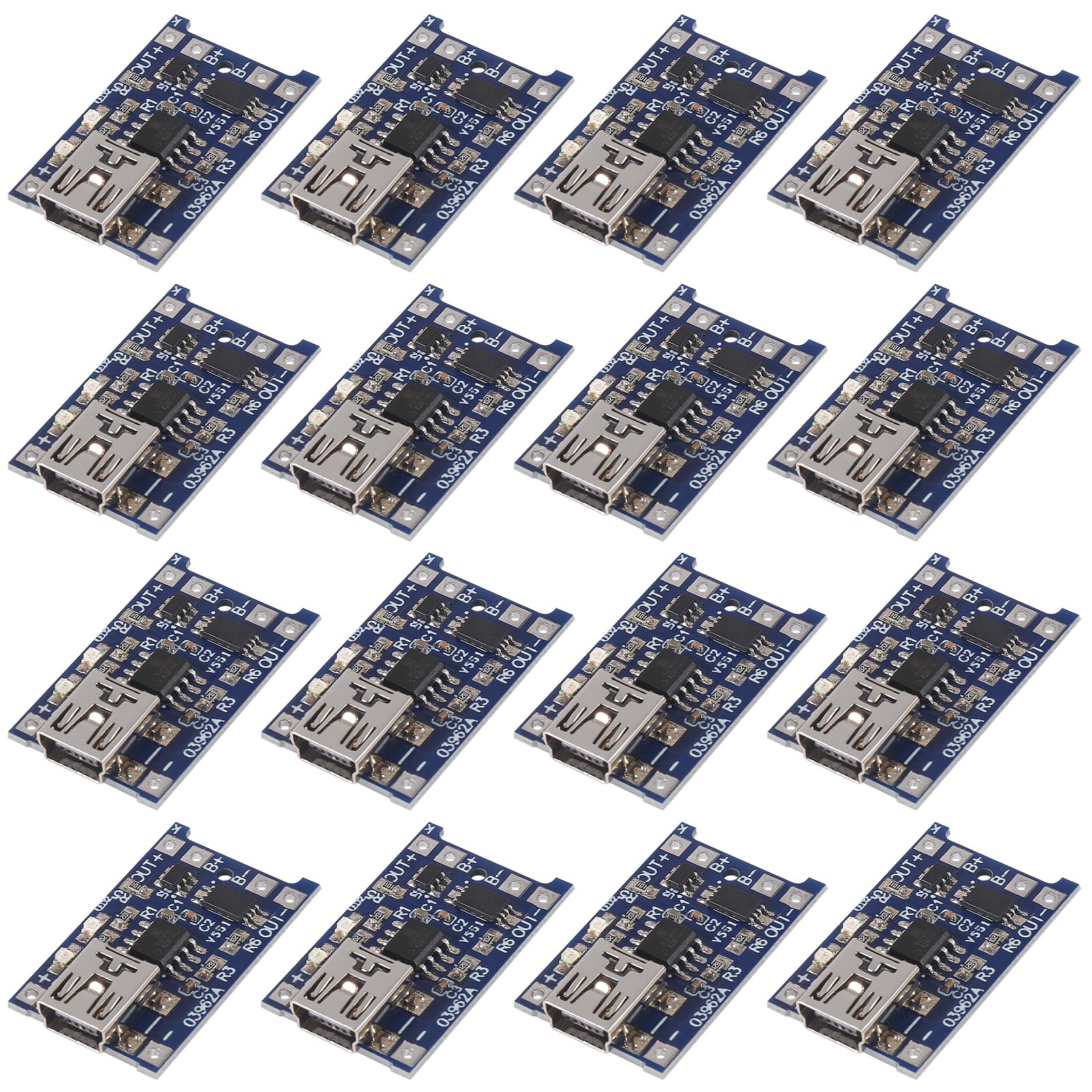
TP4056:Suitable for USB power supply and adapter power supply Charging:Battery charging board connect the battery to the B + B-, inserted into the USB female mobile phone charger;The red light is being charged,green light to full Note: When the battery is first connected, there may be no voltage output between OUT+ and OUT-. At this point, the battery can be charged by inserting a 5V voltage to activate the protection circuit. The battery is shorted from B+ B- and then connected. A charge is needed to activate the protective circuit. When using a phone charger for input,the charger should be able to output 1A or above, or it may not charge properly Over voltage range: 4.25-4.35v±0.05v
Over discharge voltage range: 2.3-3.0v±0.05v
Maximum operating current: 15A
Maximum transient current: 15-20A
Quiescent current: < 50uA
Internal resistance: < 150mΩ
Charging voltage: 12.6v - 13V
Working temperature: -40~+50℃
B+:connected to the positive electrode of the lithium battery
B-:connected to the negative electrode of the lithium battery
18650 lithium battery charger board input voltage:5V
Battery over-discharge protection voltage:2.5V
Note:
1. OUT+ and OUT- are connected to the load, such as the positive and negative poles of the moving boost board or other loads.
2. The MICRO USB socket and the + - pad next to it are the power input terminals and are connected to 5V.
Note:
The charging voltage of the TP4056 module is fixed at 4.2V,the charging current can be set externally through the resistor. When the charging current reaches the final floating voltage and drops to 1/10 of the set value, the TP4056 automatically terminates the charging cycle.
When the input voltage (AC adapter or USB power supply) is removed, the TP4056 automatically enters a low current state, reducing the battery leakage current to less than 2uA.
The TP4056 can also be placed in shutdown mode when power is available, reducing the power supply current to 55uA.